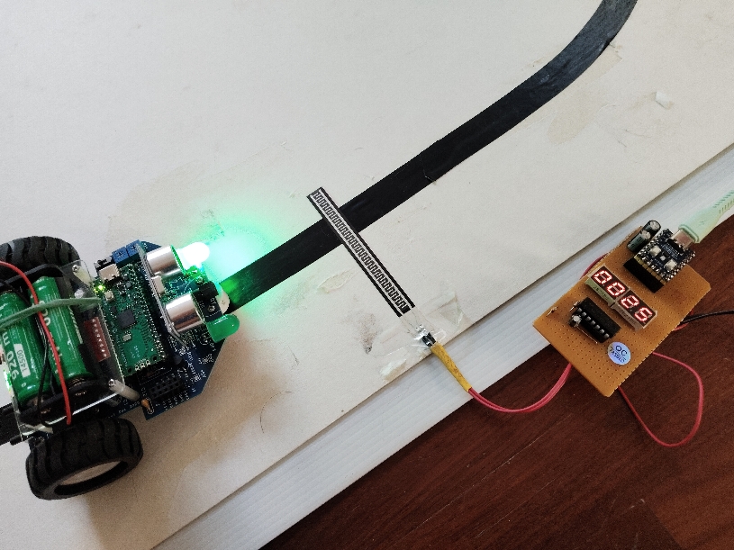
Build a simple counter display for counting the robot running test. New Piezoresistive sensor, more simple installation.
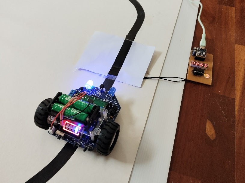
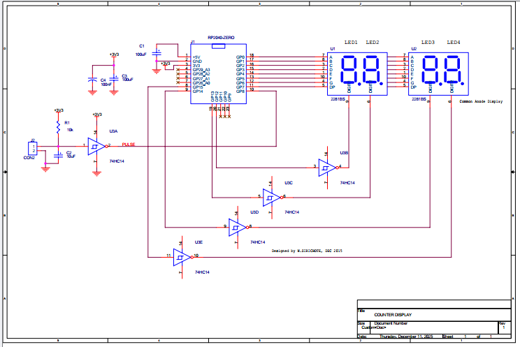
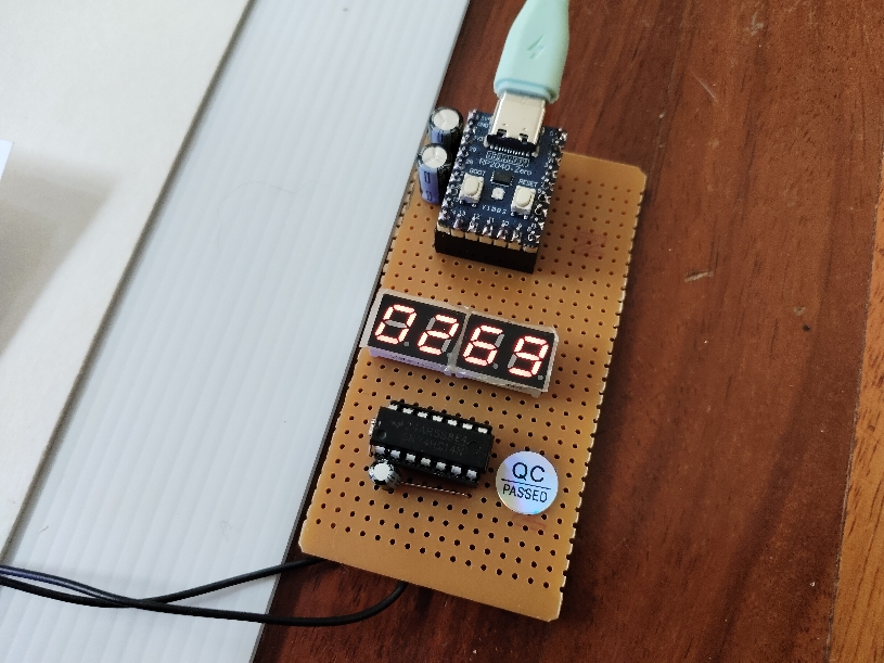
The counter display is designed for counting the number of turns Picobot runs. The circuit is built with a Pi zero board, a 4-digit display and a 74HC14 chip. The sensor is a homemade contact ON/OFF using plastic sheet and aluminum foil. The display is made of two chips, a 2281BS common anode seven segment display. The segment pins are connected from GP0 to GP7. The common pins are connected from GP12 to GP15 through the four 74HC14 gates. Display is multiplex scanning and current limitted is done by software.
The sensor is placed on the black line. When the bot passes, the contact is closed. The display module will detect the logic changes at GP8 and increment the number of turns.
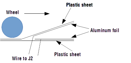
The sensor is made of a thin plastic sheet. Bend the top sheet to make the slope. Use aluminum foil to be an inductive sheet for both layers, top and bottom. Then wire them to J2. On the top layer, have the white paper and back tape as shown above. Here is the cross-section of how the sensor was made.
The control software was written in BASIC. The PI board uses the MMBASIC interpreter. BASIC program listing is shown below.
REM Counter Meter SetPin gp0, dout SetPin gp12,dout Sub led1 d Pin(gp12)=0 : Pin(gp13)=1 : Pin(gp14)=1 : Pin(gp15)=1 Write_segment d Sub led2 d Pin(gp12)=1 : Pin(gp13)=0 : Pin(gp14)=1 : Pin(gp15)=1 Write_segment d End Sub Sub led3 d Pin(gp12)=1 : Pin(gp13)=1 : Pin(gp14)=0 : Pin(gp15)=1 Write_segment d Sub led4 d Pin(gp12)=1 : Pin(gp13)=1 : Pin(gp14)=1 : Pin(gp15)=0 Write_segment d End Sub Sub write_segment d Select Case d Case 0 Pin(gp0)=0: Pin(gp1)=0:Pin(gp2)=0: Pin(gp3)=0 Case 1 Pin(gp0)=1: Pin(gp1)=0:Pin(gp2)=0: Pin(gp3)=1 Case 2 Pin(gp0)=0: Pin(gp1)=0:Pin(gp2)=1: Pin(gp3)=0 Case 3 Pin(gp0)=0: Pin(gp1)=0:Pin(gp2)=0: Pin(gp3)=0 Case 4 Pin(gp0)=1: Pin(gp1)=0:Pin(gp2)=0: Pin(gp3)=1 Case 5 Pin(gp0)=0: Pin(gp1)=1:Pin(gp2)=0: Pin(gp3)=0 Case 6 Pin(gp0)=0: Pin(gp1)=1:Pin(gp2)=0: Pin(gp3)=0 Case 7 Pin(gp0)=0: Pin(gp1)=0:Pin(gp2)=0: Pin(gp3)=1 Case 8 Pin(gp0)=0: Pin(gp1)=0:Pin(gp2)=0: Pin(gp3)=0 Case 9 Pin(gp0)=0: Pin(gp1)=0:Pin(gp2)=0: Pin(gp3)=0 End Select End Sub
Sub turn_off_display Pin(gp0)=1: Pin(gp1)=1:Pin(gp2)=1: Pin(gp3)=1 Pin(gp12)=1 : Pin(gp13)=1 : Pin(gp14)=1 : Pin(gp15)=1 End Sub Sub scan a,b,c,d led1 a led3 c
End Sub
SetPin gp8, din n=0 Do If Pin(gp8)=1 Then n=n+1 : Print n : Pause 1000 m=n i = n\1000 n=m scan i,j,k,l Pause (5) Loop |
The main program is a forever loop, detecting pin GP8. If pin GP8 is high (contact sensor is closed), then increment the counter N. And delay for 1000ms to debounce the contact. For slower bot running, the delay could be 2000ms. The counter N, maximum 9999, is converted into four digits, i, j, k, l. Subroutine scan will get four digits and write the 7-segment pattern to the display. Current limited is done by regulating with a 10% turn on power for each digit.
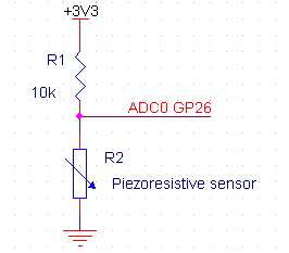
Piezoresistive sensor
The new sensor, Piezoresistive element, has been tested. The sensor can be placed on the floor. When the bot is moving on the sensor, the sensor resistance is changed from very high to low resistance. We can interface it to the PI zero ADC using a simple voltage divider with 10k pull-up.
New program with Piezoresistive sensor.
| Rem Counter Meter Rem Count the number of turn of Picobot running Rem Use Piezoresistive sensor Rem Maximum 9999 SetPin gp0, dout SetPin gp12,dout Sub led1 d Pin(gp12)=0 : Pin(gp13)=1 : Pin(gp14)=1 : Pin(gp15)=1 Write_segment d Sub led2 d Pin(gp12)=1 : Pin(gp13)=0 : Pin(gp14)=1 : Pin(gp15)=1 Write_segment d End Sub Sub led3 d Pin(gp12)=1 : Pin(gp13)=1 : Pin(gp14)=0 : Pin(gp15)=1 Write_segment d Sub led4 d Pin(gp12)=1 : Pin(gp13)=1 : Pin(gp14)=1 : Pin(gp15)=0 Write_segment d End Sub Sub write_segment d Select Case d Case 0 Pin(gp0)=0: Pin(gp1)=0:Pin(gp2)=0: Pin(gp3)=0 Case 1 Pin(gp0)=1: Pin(gp1)=0:Pin(gp2)=0: Pin(gp3)=1 Case 2 Pin(gp0)=0: Pin(gp1)=0:Pin(gp2)=1: Pin(gp3)=0 Case 3 Pin(gp0)=0: Pin(gp1)=0:Pin(gp2)=0: Pin(gp3)=0 Case 4 Pin(gp0)=1: Pin(gp1)=0:Pin(gp2)=0: Pin(gp3)=1 Case 5 Pin(gp0)=0: Pin(gp1)=1:Pin(gp2)=0: Pin(gp3)=0 Case 6 Pin(gp0)=0: Pin(gp1)=1:Pin(gp2)=0: Pin(gp3)=0 Case 7 Pin(gp0)=0: Pin(gp1)=0:Pin(gp2)=0: Pin(gp3)=1 Case 8 Pin(gp0)=0: Pin(gp1)=0:Pin(gp2)=0: Pin(gp3)=0 Case 9 Pin(gp0)=0: Pin(gp1)=0:Pin(gp2)=0: Pin(gp3)=0 End Select End Sub
Sub turn_off_display Pin(gp0)=1: Pin(gp1)=1:Pin(gp2)=1: Pin(gp3)=1 Pin(gp12)=1 : Pin(gp13)=1 : Pin(gp14)=1 : Pin(gp15)=1 End Sub Sub scan a,b,c,d led1 a led3 c
End Sub Sub wait_scan For q=0 To 200 End Sub Sub update_display m=n i = n\1000 n=m End Sub
SetPin gp26, araw n=0 Do Print Pin(gp26) If Pin(gp26) <2000 Then n=n+1 : update_display : wait_scan scan i,j,k,l Pause (5) Loop |
Pin PG26 (ADC0) is set to analog RAW readings. The main program prints the ADC0 value. When the value is less than 2000, i.e. the bot makes pressure on the sensor, the variable N is incremented.
See the sample video below.
Download
Source code in BASIC program , BASIC Interpreter for PI zero board
More technical information, please contact Wichit Sirichote, wichit.sirichote@gmail.com
Last updated December, 2025
December 2025