Simple design educational robot built with PI Pico. Using MMBASIC interpreter for controlling the bot
Build a simple robot controlled by PI Pico and an MMBasic interpreter. The robot controller is a PI Pico compatible using the RP2040 Microcontroller. The robot has two rear wheels driven by the N20 motor. The motor driver is a TB6612 chip. The built-in sensors are the SR04 ultrasonic ranger, line tracking Infared sensor, HM338 IR Receiver, IR Transmitter, and two-button tact switches. In addition, the bot also has a stereo amplifier for two channels' sound output. The bot can be powered by two cells of a 14500 Li-ion battery or a +7.4V Li-ion battery pack.
The MMBASIC interpreter provides a very interactive learning system for studying how to control the bot. Under command mode, the subroutine that controls the motor can be tested immediately by typing the subroutine name. The motor action will respond directly.
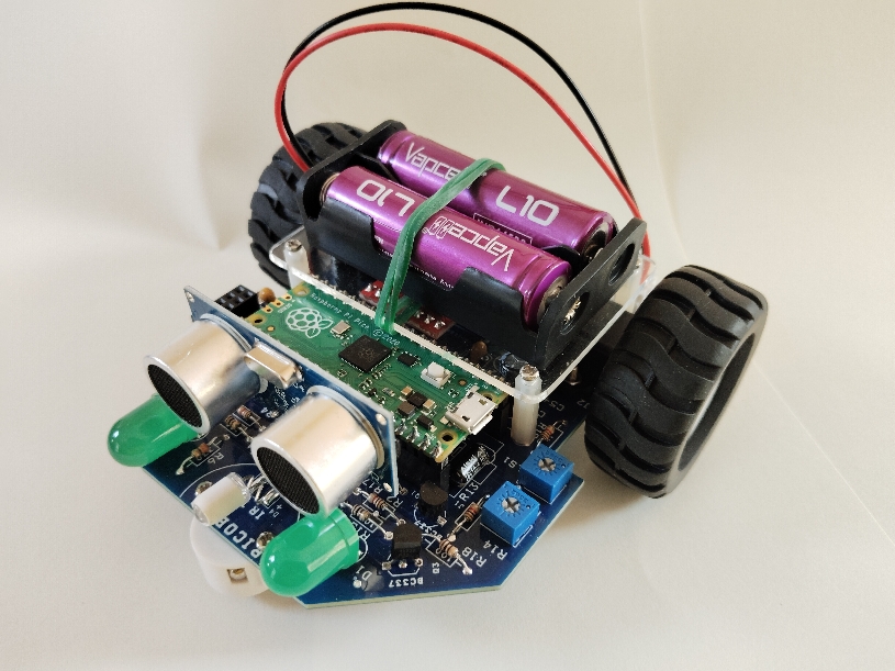
Picobot v1.0 with Li-ion battery
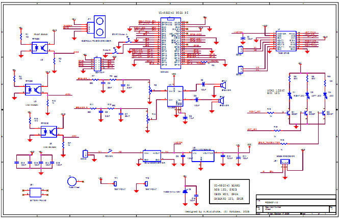
The main controller, J1, is a PI Pico compatible board. The bot layout is shown below (no battery). The bot platform is made with an epoxy PCB. Most of the components are placed on the top layer. The line sensors and speaker are placed on the bottom side. The battery holder will be placed on the plastic stand.
The N20 gear motor left and right sides are fixed on the PCB with M2 nut directly.
The IR Receiver is placed on the back side and the IR transmitter on the front side.
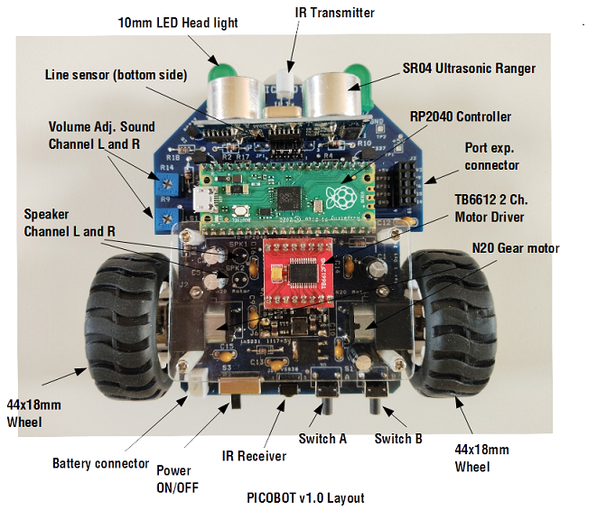
The sensor, LED indicator and motor connections to the PI board are shown below.
Device |
Port pin |
Port function |
Line sensor1, U3 |
GP26 |
Analog, ADC0 |
Line sensor2, U5 |
GP27 |
Analog, ADC1 |
Line sensor3, U2 |
GP28 |
Analog, ADC1 |
SR04 Ultrasonic ranger, Trigger pin |
GP16 |
Digital out |
SR04 Ultrasonic ranger, Echo pin |
GP17 |
Digital in |
Start button, A |
GP7 |
Digital in, pullup |
Stop button, B |
GP8 |
Digital in , pullup |
IR Receiver, JS1 |
GP4 |
IR Rx |
IR Transmitter, D4 |
GP5 |
IR Tx |
Head light, D1 |
GP2 |
Digital out |
Head light, D2 |
GP3 |
Digital out |
LEFT PWM |
GP1 |
PWM |
/LEFT_DIR |
GP13 |
Digital out |
LEFT_DIR |
GP12 |
Dgital out |
RIGHT PWM |
GP0 |
PWM |
/RIGHT_DIR |
GP11 |
Digital out |
RIGHT_DIR |
GP10 |
Digital out |
SPEAKER_L |
GP18 |
SOUND LEFT CH |
SPEAKER_R |
GP19 |
SOUND RIGHT CH |
Connecting the bot to terminal
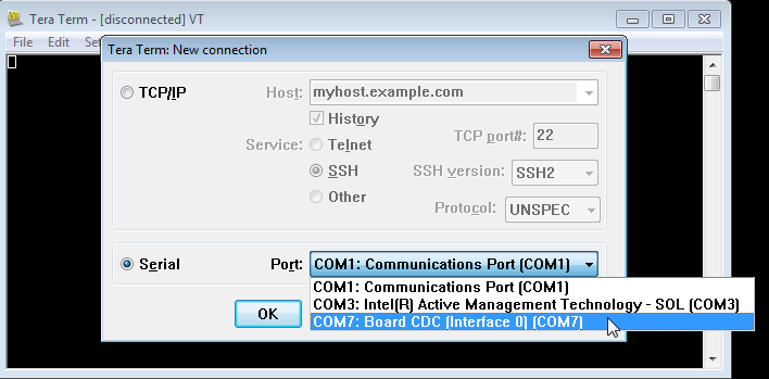
The PICObot uses a terminal for BASIC program writing. When connected to the terminal, Windows will provide a given COM port using the CDC interface device. The example below shows COM7 is now available.
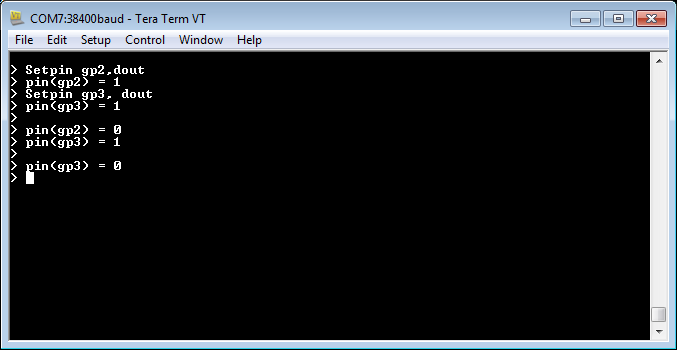
When the terminal is connected, press the ENTER key, the MMBasic will send a prompt.
Under prompt, we can test hardware directly. Here is an example of a command that sets pins GP2 and GP3 to be digital output.
Command Pin(gp2) = 1 will write logic one to GP2. We will see the headlights turned on.
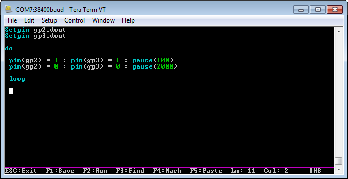
MMBASIC has a built-in editor for writing the BASIC program. Under command mode, type edit, will open the editor screen.
Suppose we enter the program below. Press F1 to save the program and exit from the editor.
Then press command >RUN, you will see the flashlight on the head lamp. To stop it, press Ctrl C..
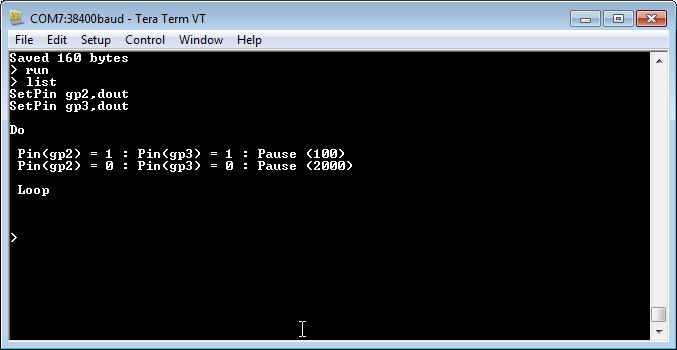
We can list the program with the command >List
The program being tested under the built-in editor can be saved to the host computer by using XMODEM protocol. The short key is F12. For uploading the BASIC program, on a terminal, we will use function file transfer, XMODEM receive mode.
We can also transfer the BASIC program from the host PC to the bot by using XMODEM receive, or key F11. The host terminal will use file transfer, XMODEM transmit mode.
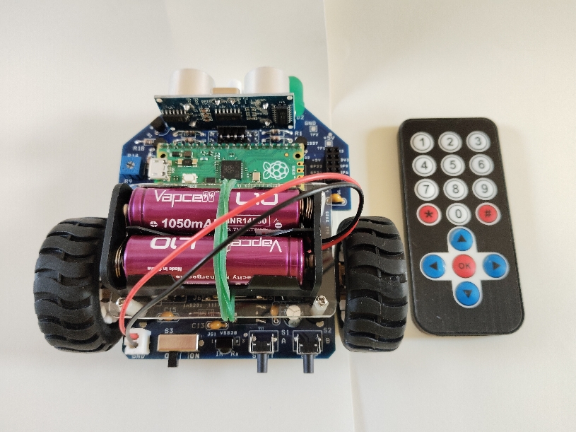
The IR receiver accepts the code generated by a cheap remote control as shown. The bot uses GP4 for the IR receiver. A simple program that reads key code from remote control is shown below.
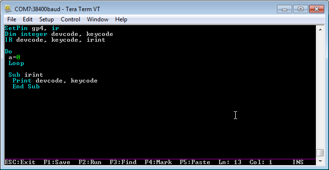
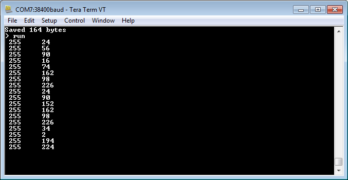
When we running the program, we can press the remote control, we will see the printing of ID code and key code on the screen. From these codes, we can then use the remote key to control the bot. More programs are available in the LAB BOOK.
PARTS LIST Resistors (all resistors are 1/8W +/-5%) Double side PCB JP1 HC-SR04 ULTRASONIC RANGER |
Here is the sample video of line tracking test. See the complete program in LAB book.

Download
BASIC programs , MMBasic Firmware and Manual
More technical information, please contact Wichit Sirichote, wichit.sirichote@gmail.com
Last updated November, 2025
November 2025