What is MTK51?
Download
Schematic
Contact
8051 Instruction Set
Build a single board computer with a 8051-compatible microcontroller, ATMEL 89S52. Available now, Bare PCB + PLD chip only $55.

MTK51 is a single board computer that uses the ATEML 89S52 microcontroller as the CPU. The board provides a 32kB RAM (code memory) for user program and a 32KB ROM for monitor program. The board is designed for studying the microcontroller hardware and instruction coding. We can enter HEX code directly to the code memory and test the code with single step running, check the result of the operation with user registers. The kit also provides more devices interfacing, e.g. ADC, EEPROM, RTC, RELAY, Programmable Port, serial ports RS232, and RS485. The MCU can run both single chip or expand modes as well.
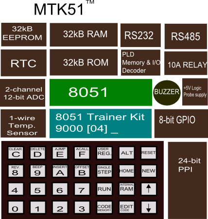
Block Diagram of the MTK51 8051 Microcontroller Trainer.
Hardware features:
- MCU: ATMEL 89S52 @11.0592MHz, 40-pin DIP package 8051-compatible microcontroller chips,
- Memory: 32kB RAM, 32KB monitor ROM, 256 bytes on-chip RAM,
- GPIO: 8255 PPI, P1, P3,
- DISPLAY: 16x2 Text LCD,
- Keypad: 28-key, 16-HEX key, 12-function key,
- ADC: LTC1298, MCP3202, 2-channel 12-bit resolution,
- RTC: DS1307 I2C interface real-time clock with +3V Lithium battery backup,
- EEPROM: 32kB 24LC256,
- Temperature sensor: DS1820,
- RELAY: 10A 250VAC relay with NO-C-NC terminal,
- Serial port: 9600 RS232 and RS485,
- Optional keyboard: PS2 interface connector.
The monitor software features:
- Enter hex code directly using the 16-key hex key,
- Single step running with user registers display,
- Run user code full speed,
- Display code and data memory,
- Offset byte calculation for relative addressing mode,
- Insert AJMP and ACALL hex code to the code memory,
- Insert byte and delete byte,
- Clear code memory,
- Quick home location key.

Schematic of the MTK51 8051 Microcontroller Trainer.
Simple program demos entering the machine code and execution with single step.
The code shown below will increment the accumulator content by one. The hex code for this simple program has only 3 bytes, i.e. 04 01 00. The video shows how to enter the hex code, how to insert the AJMP instruction and how to run it with key STEP. We will see the right-hand 8-bit LED (GPIO3) counting up. See the video
| ADDRESS | HEX CODE | LABEL | INSTRUCTION | COMMENT |
| 9000 | 04 | MAIN | INC A | A=A+1 |
| 9001 | 01 00 | AJMP MAIN | go back main |
Running full speed with forever loop program
Another sample is the forever loop running. The accumulator contents will write to GPIO3 using indirect mode through DPTR, then increment and the delay subroutine will be called. The program is repeated forever with AJMP MAIN instruction. The subroutine DELAY is simple delay code by counting two registers, R7 and R6.
| ADDRESS | HEXCODE | LABEL | INSTRUCTION | COMMENT |
| 9000 | 90 04 00 | MAIN | MOV DPTR,#400H | DPTR=400H |
| 9003 | F0 | MOVX @DPTR,A | A->GPIO3 | |
| 9004 | 04 | INC A | A=A+1 | |
| 9005 | 11 09 | ACALL DELAY | CALL DELAY | |
| 9007 | 01 00 | AJMP MAIN | goback main | |
| 9009 | 7F 00 | DELAY | MOV R7,#0 | |
| 900B | 7E 00 | INNER | MOV R6,#0 | |
| 900D | DE FE | DJNZ R6,$ | ||
| 900F | DF FA | DJNZ R7,INNER | ||
| 9011 | 22 | RET |
Bare PCB + PLD chip, only $55 + free shipping!

Pay now for bare PCB and preprogrammed PLD chip only $55 + free shipping. PayPal with my email directly wichit.sirichote@gmail.com
More information please contact: Wichit Sirichote, wichit.sirichote@gmail.com
Download:
Monitor program
PLD's
JEDEC file
Hardware Schematic
BOM
Keypad Drawing SVG file (4 sheets on A4 size paper) using DrawFreely Inkscape
Keypad label can be made easily with sticker paper covered with the clear one.
MTK51 LAB BOOK (XML file)
LAB 1 Introduction to MTK51
LAB2 Programming Registers
LAB 3 Internal memory and STACK
LAB 4 I/O Port & GPIO
LAB 5 Timer and Interrupt
LAB 6 LCD
LAB 7 Serial Port I
LAB 8 Serial Port II