Tiny
2313 Project Development Board
Tahan
Prahara,
Email :
tahan_prahara@yahoo.co.id
YM:
tahan_prahara
This is my first time using the AVR.
I like to learn using the ATTiny 2313, because it is
faster than MCS-51, cheap and the circuit is very simple. The chip has only 20
pins. I was interested because I want to build a simple line follower robot
controlled by this MCU.
The circuit has built in voltage
regulator, the LM7805 and the ISP Header for program loading. The DC input
circuit also has protection diode 1N4002.
DOWNLOAD EXPRESS PCB FILE: AT-Tiny2313.zip

Figure 1.
Hardware Schematic
Notes:
1 The XTAL can be 4MHz, 8MHz, or 11.0592MHz.
2 DC input voltage using the AC adapter can be 6V-15V.
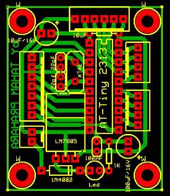
Figure 2.
Component placement.
ISP Programmer
The ISP loader cable can be made
easily from the circuit shown in Figure 3. The connector is DB25 male type. The
cable length should be less than 1m. This loader is compatible with most of the
desktop LPT port.

Figure 3.
ISP Programmer Cable (STK200)
Using the CodeVision
AVR
1.
Create New Project by click File ->
New
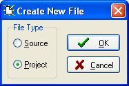
2. Click Yes to use The CodeWizardAVR.

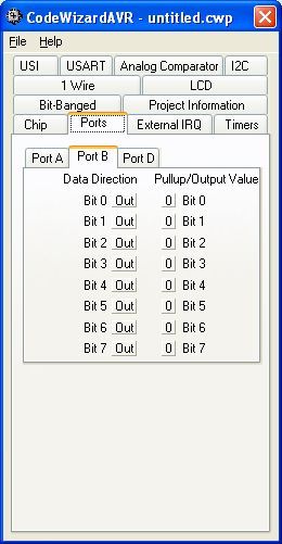
3. Set the Wizard like this. (for XTAL
11.0592 MHz). Then Click File -> Generate, Save and Exit


4. Insert your program (Bold text)
This program was produced by the
CodeWizardAVR V1.25.9 Evaluation
Automatic Program Generator
©
Copyright 1998-2008 Pavel Haiduc,
HP InfoTech s.r.l.
http://www.hpinfotech.com
Project : Tahan Prahara Test
Version :
Date : 5/11/2008
Author
: Freeware, for evaluation and
non-commercial use only
Company :
Comments:
Chip
type : ATtiny2313
Clock
frequency : 11.059200 MHz
Memory
model : Tiny
External SRAM size
: 0
Data Stack
size : 32
*****************************************************/
#include <tiny2313.h>
#include <delay.h>
// Declare your
global variables here
void main(void)
{
// Declare
your local variables here
// Crystal Oscillator division
factor: 1
#pragma optsize-
CLKPR=0x80;
CLKPR=0x00;
#ifdef
_OPTIMIZE_SIZE_
#pragma optsize+
#endif
// Input/Output
Ports initialization
// Port A initialization
// Func2=In Func1=In Func0=In
// State2=T State1=T State0=T
PORTA=0x00;
DDRA=0x00;
// Port B initialization
// Func7=Out Func6=Out Func5=Out
Func4=Out Func3=Out Func2=Out Func1=Out Func0=Out
// State7=0 State6=0 State5=0
State4=0 State3=0 State2=0 State1=0 State0=0
PORTB=0x00;
DDRB=0xFF;
// Port D initialization
// Func6=In Func5=In Func4=In
Func3=In Func2=In Func1=In Func0=In
// State6=T State5=T State4=T State3=T
State2=T State1=T State0=T
PORTD=0x00;
DDRD=0x00;
// Timer/Counter 0 initialization
// Clock source: System Clock
// Clock value: Timer 0 Stopped
// Mode: Normal top=FFh
// OC0A output: Disconnected
// OC0B output: Disconnected
TCCR0A=0x00;
TCCR0B=0x00;
TCNT0=0x00;
OCR0A=0x00;
OCR0B=0x00;
// Timer/Counter 1 initialization
// Clock source: System Clock
// Clock value: Timer 1 Stopped
// Mode: Normal top=FFFFh
// OC1A output: Discon.
// OC1B output: Discon.
// Noise Canceler: Off
// Input Capture on Falling Edge
// Timer 1 Overflow Interrupt: Off
// Input Capture Interrupt: Off
// Compare A Match Interrupt: Off
// Compare B Match Interrupt: Off
TCCR1A=0x00;
TCCR1B=0x00;
TCNT1H=0x00;
TCNT1L=0x00;
ICR1H=0x00;
ICR1L=0x00;
OCR1AH=0x00;
OCR1AL=0x00;
OCR1BH=0x00;
OCR1BL=0x00;
// External Interrupt(s)
initialization
// INT0: Off
// INT1: Off
// Interrupt on any change on pins
PCINT0-7: Off
GIMSK=0x00;
MCUCR=0x00;
// Timer(s)/Counter(s) Interrupt(s)
initialization
TIMSK=0x00;
// Universal Serial Interface
initialization
// Mode: Disabled
// Clock source: Register &
Counter=no clk.
// USI Counter Overflow Interrupt:
Off
USICR=0x00;
// Analog Comparator initialization
// Analog Comparator: Off
// Analog Comparator Input Capture
by Timer/Counter 1: Off
ACSR=0x80;
while (1)
{
//
Place your code here
PORTB=0b00000000;
delay_ms(2000);
// Delay 2000 mS = 2 S
PORTB=255;
delay_ms(3000);
PORTB=0x00;
delay_ms(2000);
PORTB=1;
Delay_us(10)
//
Delay 10 uS
};
}
5. Click Project -> Configure, click tab After
Make then,

Mark the Program the Chip, after
that click OK!

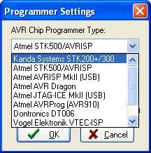
6. If this is your first time using CodeVision
AVR you need to setup the programmer. Just click on Setting ->
Programmer.

Click on Kanda Systems
STK200+/300, then click OK.
7. To compile and programming the chip, click Project ->
Make or just click on red arrow buttom!
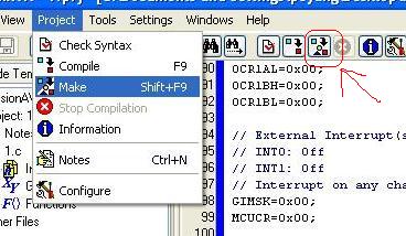
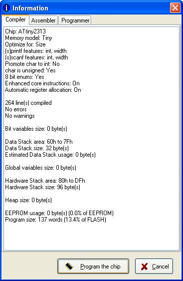
If you get
no error and no warning. You can
just click Program the Chip buttom. The hex
code will be programmed automatically.

Tahan Prahara and Pujo
at Line Follower Competition, Galelobot 2008.

 I'm thinking what can I do for the world