ATMEL AVR ATMega 8535/16/32
and
ATMEL AT89S5x Family
Learning Kit
Eko Yulianto,diynesia@gmail.com
Blog,www.diynesia.xyz
Build the ![]() and
and ![]() AVR and AT89S5x Family learning boards with I/O interfacing modules.
AVR and AT89S5x Family learning boards with I/O interfacing modules.
Both Mainboard Features

Figure 1 Mainboard layout for ATMega 8535/16/32
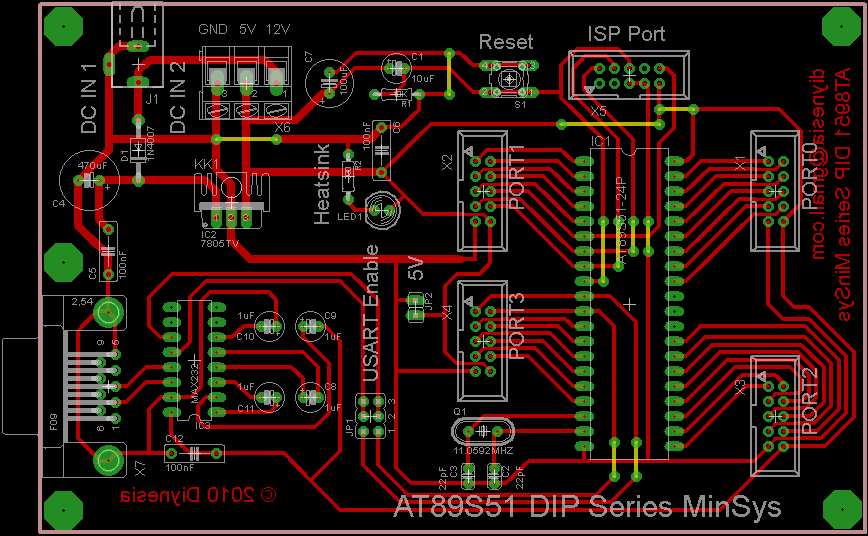
Figure 2 Mainboard layout for AT89S5x Family
I/O Modules:
LED Board
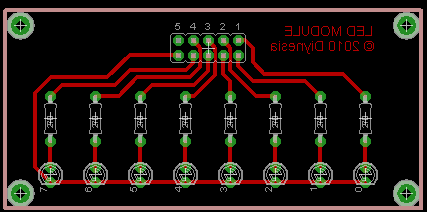

Figure 3 LED Module Single and Double
Tact Switch Module
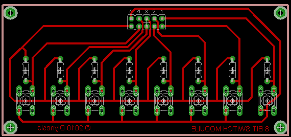
Figure 4 Tact SwitchModule
LCD Module

Figure 5 LCD Module
Keypad Module
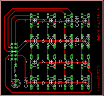
Figure 6 Keypad Module
RTC and 1-Wire Temperature Sensor Module
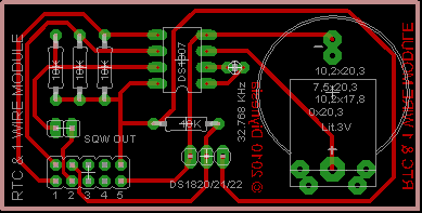
Figure 7 RTC and 1-Wire Temperature Sensor Module
ISP Header Pin Configuration

Figure 8 Signals of the ISP header
Download the complete file here : kit_module_new.zip.
The zip file contains all PCB boards, include schematic for both mainboard.
For the board with no schematic included (figure 3 - 7), you can make it yourself, is easy to figure out the schematic from the PCB board.
If you have any question, suggestion or maybe you find a bug, I'll very grateful if you contact me at : diynesia@gmail.com or www.diynesia.xyz
Updated: August, 3rd, 2016.