|
|
|
Close Help | ||||||||||||||
Priyank
Patil, priyank.patil@gmail.com
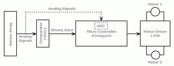
Block Diagram
The robot uses IR sensors to
sense the line, an array of 8 IR LEDs
(Tx) and sensors (Rx), facing the ground has been
used in this setup. The output of the sensors is an analog signal which depends
on the amount of light reflected back, this analog signal is given to the comparator
to produce 0s and 1s which are then fed to the µC.
|
L4 |
L3 |
L2 |
L1 |
R1 |
R2 |
R3 |
R4 |
Left
Center
Right
Sensor Array
Starting from the center, the
sensors on the left are named L1, L2, L3, L4 and those on the right are named
R1, R2, R3, R4.
Let us assume that when a sensor is on the line it reads 0 and when it is off the line it reads
1
The µC decides the next move so
as to position the robot such that L1 and R1 both read 0 and the rest read 1.
|
L4 |
L3 |
L2 |
L1 |
R1 |
R2 |
R3 |
R4 |
|
1 |
1 |
1 |
0 |
0 |
1 |
1 |
1 |
Left
Center
Right
Desired State L1=R1=0, and Rest=1
Algorithm:
1. L= leftmost sensor which reads 0; R= rightmost sensor which
reads 0.
If no sensor on Left (or Right) is 0 then L (or R) equals
0;
For example:
|
L4 |
L3 |
L2 |
L1 |
R1 |
R2 |
R3 |
R4 |
|
1 |
0 |
0 |
1 |
1 |
1 |
1 |
1 |
Left Center
Right
Here L=3 R=0
|
L4 |
L3 |
L2 |
L1 |
R1 |
R2 |
R3 |
R4 |
|
1 |
1 |
0 |
0 |
0 |
0 |
0 |
0 |
Left
Center
Right
Here L=2 R=4
2. If all sensors read 1 go to step 3,
else,
If
L>R Move Left
If L<R Move Right
If L=R Move Forward
Go to step 4
3. Move Clockwise if line was last
seen on Right
Move Counter Clockwise
if line was last seen on Left
Repeat step 3 till line is found.
4. Go to step 1.
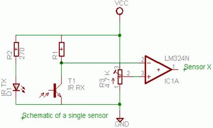
Sensor Circuit
For
a good voltage swing from the potential divider use
R1=
Sqrt (Resistance of sensor when light falls on it * Resistance
of sensor when light does not fall on it)
Motor Interface and
Control Circuit:
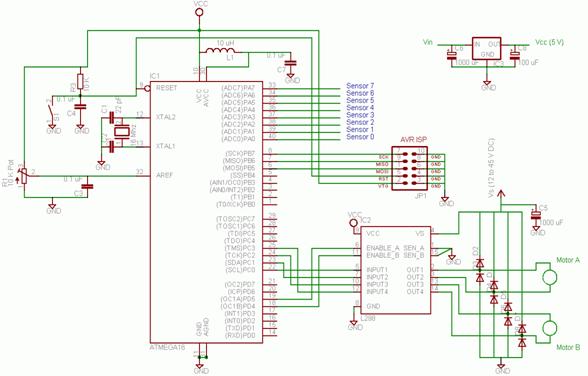
The 8 sensors are connected
to PORTA.
You need not connect anything
to AVCC and AREF, it is required only if ADC is used.
The L298 Motor Driver has 4 inputs to control the
motion of the motors and two enable inputs which are used for switching the
motors on and off. To control the speed of the motors a PWM waveform with
variable duty cycle is applied to the enable pins. Rapidly switching the
voltage between Vs and GND gives an effective voltage between Vs and GND whose
value depends on the duty cycle of PWM. 100% duty cycle corresponds to voltage
equal to Vs, 50 % corresponds to 0.5Vs and so on. The 1N4004 diodes are used to
prevent back EMF of the motors from disturbing the remaining circuit.
You may drop your feedback at
priyank.patil@gmail.com
Download: