Wichit Sirichote, wichit.sirichote@gmail.com
Experiments interfacing modules with the 8051 Project Board, sample code and wiring schematic
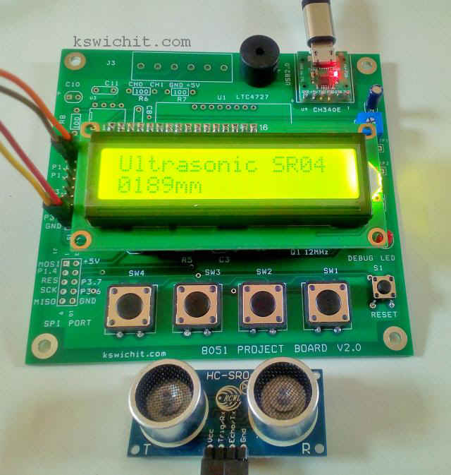
The 8051 project board provides additional I/O ports for interfacing with the sensor modules and actuators. The sensor modules can be interfaced with simple I/O bits or high speed SPI port. The on-board display, keypad, buzzer and USB port are available for making a given instrument easily. The source code is for Mikro-C for 8051 compiler.
1. Ultrasonic ranger, SR04 module.
Wiring diagram
The SR04 module has 4-pin. VCC, TRIG, ECHO and GND. Trigger pin tied to P1.0, is used to trig the module to send the bursts of sound wave. The echo signal is positive pulse with duration proportional to the time of flight of the sound wave. This signal is tied to P1.1/T2EX pin. The end of echo signal will be detected by Timer2 negative edge triggering.
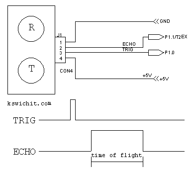 |
| Wiring diagram and signals |
Using Timer2 capture mode
To measure the period of echo signal, the internal oscillator is set as the 1 MHz timebase. When trigger is activated, TR2 is enabled, timer2 will be incremented counting. At T2EX pin, the negative edge of echo signal will make the capture pulse. Timer2 count value will be transferred to Capture registers.

The code begins with serial port and timer2 initialization. The MCU uses 12MHz, oscillator, so the standard 4800 BAUD can be generated using Timer1. Timer2 is used for 16-bit capture mode with internal clock time base.
The main loop enters with firing trigger signal, wait for echo to start HIGH. When the negative edge, transition from HIGH to LOW is detected, stop the timer2 and the capture registers are read.
The readings is the period of echo signal in micro second unit. Then convert it into length in mm unit. The length is sent to terminal and LCD display.
Buzzer alarm is the sample code for a given range detection within 100mm to 300mm. .
// Ultrasonic ranger SR04
 // using capture mode of Timer2 with negative edge echo signal
 // written by wichit sirichote, May 2020
// source code is for Mikro-c for 8051
// Lcd module connections sbit LCD_RS at P2_6_bit; sbit LCD_EN at P2_7_bit; sbit LCD_RW at P2_5_bit; sbit LCD_D4 at P0_4_bit; sbit LCD_D5 at P0_5_bit; sbit LCD_D6 at P0_6_bit; sbit LCD_D7 at P0_7_bit; // End Lcd module connections sbit LED at P1.B2; sbit trigger at P1.B0; sbit echo at P1.B1; sbit beep at P3.B7; long j; long k; char buffer[8]; char txt1[] = "Ultrasonic SR04"; /* sound velocity Ref: http://www.sengpielaudio.com/calculator-speedsound.htm At 0°C is ?0 = 1.293 kg/m3, Z0 = 428 N·s/m3, and c0 = 331.3 m/s At 15°C is ?15 = 1.225 kg/m3, Z15 = 417 N·s/m3, and c15 = 340 m/s At 20°C is ?20 = 1.204 kg/m3, Z20 = 413 N·s/m3, and c20 = 343 m/s At 25°C is ?20 = 1.184 kg/m3, Z25 = 410 N·s/m3, and c25 = 346 m/s or 0.0346 cm/us */ // initialize baud rate generator 4800 using Timer1
void init_UART()
{
SCON = 0x50; /* SCON: mode 1, 8-bit UART, enable rcvr */
PCON |= 0x80; // smod=1
TMOD |= 0x20; /* TMOD: timer 1, mode 2, 8-bit reload */
TH1 = 0xf3; /* TH1: reload value for 4800 baud */
TR1_bit = 1; /* TR1: timer 1 run */
TI_bit = 1; /* TI: set TI to send first char of UART */
} void init_captureT2()
{
T2CON = 0x09; // capture mode Timer2
TH2 = 0;
TL2 = 0;
} void sound_beep()
{
beep = 0;
Delay_ms(50);
beep = 1;
}
void main() {
 AUXR = 0; // enable onchip external RAM accessing

   init_UART();

   init_captureT2();

   trigger=0;
   P0= 0;
   LCD_RW =0;
   Lcd_Init(); // Initialize Lcd
Lcd_Cmd(_LCD_CLEAR); // Clear display Lcd_Cmd(_LCD_CURSOR_OFF); // Cursor off Lcd_Out(1, 1, txt1); Delay_ms(100); UART1_Write_Text("\r\nUltrasonic ranger v1.0");
while (1) {
 init_captureT2();

   trigger = 1;
   Delay_us(10);
   trigger = 0;

   Delay_us(5);

   while(echo==0)
   ;
   TR2_bit = 1;
   EXEN2_bit = 1;

   while(EXF2_bit==0)
   ;

   EXF2_bit = 0;
   TR2_bit = 0;
   EXEN2_bit = 0;
   j =0;
   j |= RCAP2H;
   j <<=8;
   j |= RCAP2L;
   j = j/2; // time of flight/2

   k = 346*j/1000; // for 25C

   LED = 0;

   sprintl(buffer,"\r\n%lu",k); // display in mm
   UART1_Write_Text(buffer);

   sprintl(buffer,"%04lumm",k); // display in mm
   Lcd_Out(2,1,buffer);


   LED = 1;

   if( (k > 100) && (k <300) ) sound_beep();

   Delay_ms(500);
} } |
| Source code listing |
The readings are also sent to terminal.
 |
Download