Available now replacement kit.
This page describes how to build the microcontroller circuit for replacing the E21 digital clock. The obsolete SCL5455E automotive clock integrate circuit was replaced by the ATMEL 89S52 8-bit microcontroller running with a 12MHz oscillator. The firmware is timer0 interrupt that produces 10ms tick. This tick is used to produce 12/24 clock. The board was modified using wire soldering. The replacement board can be plugged back to the power terminals provided by the tachometer board directly.

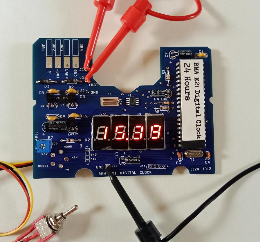
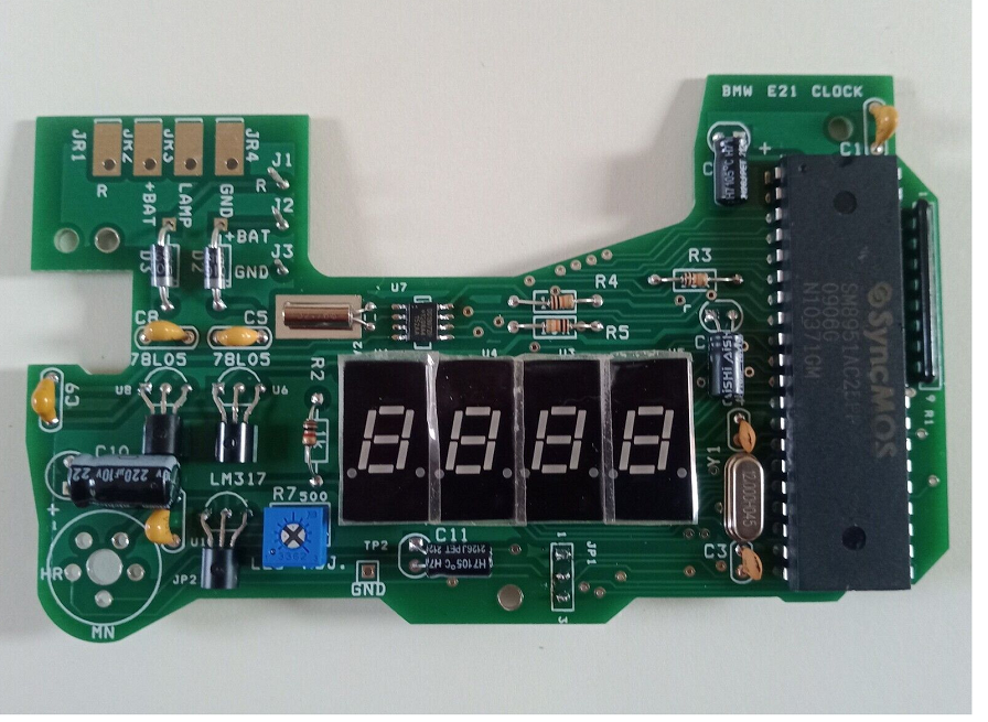
Figure 1: The replacement board using the 89S52 microcontroller.
The original clock board built with the SCL5455E chip is shown in Figure 2.
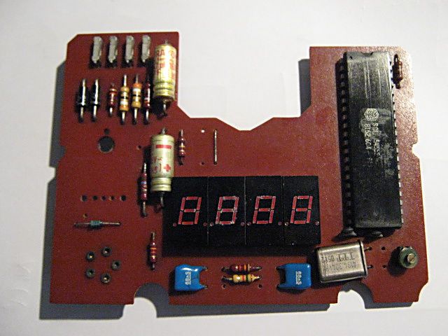
Figure 2: The original PCB using the SCL5455E.

Figure 3: The bottom copper layer.
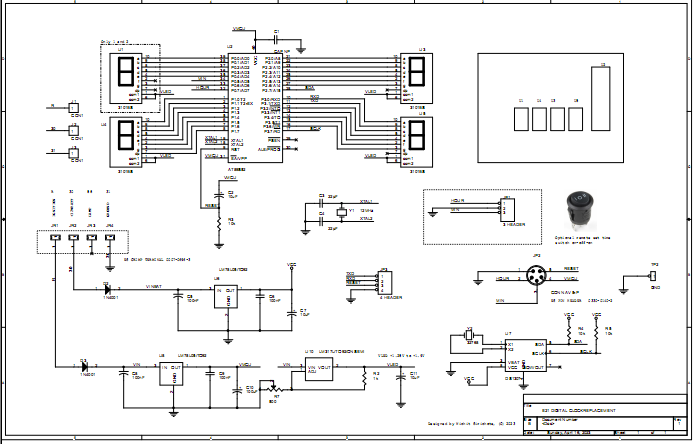
Hardware Schematic
The microcontroller, U2 is the 8-bit 89S52 microcontroller. The chip can be programmed using Asim loader through the ISP port easily. The display has 4-digit, using the HP5082-7331 common anode 7-segment LED. The 7-segment LED is driven with sinking current through the microcontroller parallel port, P0, P1, P2 and P3. The power source for driving such LED is supplied from +3.3V voltage regulator through ignition power terminal (R). U2 is powered by D4, +3.3V zener diode through +12V battery terminal. When ignition switch is turned off, , the LED display will be turned off, but the microcontroller instead is still functioning by a +12V battery power. The power drawn by D4 and microcontroller is about 20mA @+12V or 240mW. When the display on, total power will be 1.2W. J1 is soldering pad used for selecting between 12 or 24 clock.

Figure 4: Hardware schematic.
HP 5082-7731 seven segment LED
The part number for 7-segment LED is HP 5082-7731 common anode LED.
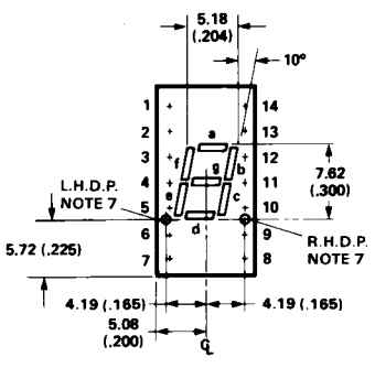
Figure 5: Dimension of HP5082-7331 LED (inches).
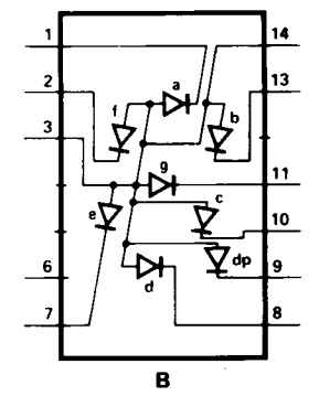
Figure 6: Pin designation for each segments.
Rebuild the Board
The original board was rebuilt by removing copper traces at the 40-pin pads, 7-segment pads and power pads. Circuit connection is done by wire soldering.
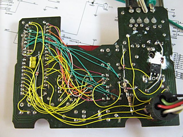
Figure 7: Wire soldering and copper traces removing.
Bill Of Materials May 23,2010 11:41:26 Page1 Item Quantity Reference Part ______________________________________________ 1 2 C1,C3 30pF 2 1 C2 10uF 3 2 C4,C5 47uF 16V 4 1 C6 0.1uF 5 4 D1,D2,D5,D6 1N4001 6 1 D4 1N5226 7 1 JP1 CONN AV 5-P 8 4 JR1,JR2,JR3,JR4 CONN RECT 1 9 1 J1 CON2 10 1 Q1 12MHz Xtal 11 1 R1 4.7k 12 1 R2 10k 13 1 R3 1k 0.5W 14 4 U1,U3,U4,U5 HP5082-7731 15 1 U2 AT89S52 16 1 U6 LM117A/+3.3V |
Software
The firmware produces 10ms tick by using timer0 interrupt. The realtime clock is updated every 10ms. The display is updated every second and when h or min button are pressed.
/*
   Replacement for E21 clock SCL5455E chip
   The 89S52 microcontroller running at 12Mhz uses Timer0 to produce 10ms tick.
   Check xtal oscillation frequency by measuring the ALE pin. The ALE clock is 1/6 of Xtal frequency.
   Fine adjusment may be done by TL0 reload value.

   TIME key adjust time within +/-2mins at a given hour to the correct clock.
   Hour and Min keys have repeat function.

    Copyright (C) 2010 W.Sirichote, wichit.sirichote@gmail.com

    This program is free software: you can redistribute it and/or modify
    it under the terms of the GNU General Public License as published by
    the Free Software Foundation, either version 3 of the License, or
    (at your option) any later version.

    This program is distributed in the hope that it will be useful,
    but WITHOUT ANY WARRANTY; without even the implied warranty of
    MERCHANTABILITY or FITNESS FOR A PARTICULAR PURPOSE.  See the
    GNU General Public License for more details.

    You should have received a copy of the GNU General Public License
    along with this program.  If not, see <http://www.gnu.org/licenses/>.
*/
#include <reg52.h> /* special function register declarations */
#include <stdio.h>
sfr WDTRST = 0xa6; sbit key_hour = P2^7; sbit key_min = P3^7; sbit H24_12 = P0^7; // select between 24 or 12 clock, open for 24, Ground for 12 unsigned char sec100,sec,min,hour,flag1; unsigned char hour_max; unsigned char i,digit, buffer[4];
char cputick,key,delay,count1;
char press_hour=0;
char press_min=0;
unsigned char convert[10] = {0x3F,0x06,0x5b,0x4f,0x66,0x6d,0x7d,0x07,0x7f,0x6f};
char timer4=0;
char timer5=0;
char timer6=0;
void time(); void time2(); void timeToBuffer(); void write_digit(); void set_hour(); void set_min(); void scan_key(); void release_key(); void auto_repeat();
void clear_wdt();
static timer0int (void) interrupt 1 using 1 {
   TH0 |= 0xd8; // reload timer 0 with d8f0h
   //TL0 |= 0xf0; // actual calculation is 0xf0
   TL0 |= 0xff; // adjustment
   cputick++;
   time(); // update realtime clock
   // P0^=0x80; // toggle P0.7 for 100 Hz timer base (100/2=50Hz)

   }
void long_delay(unsigned int j)
   {
   unsigned int i;
   for(i=0; i<j; i++)
   clear_wdt();
   }
void clear_wdt() //every 8191 Machine Cycle
   { //~8 ms
   WDTRST = 0x1e;
   WDTRST = 0xe1;
   }
void check_cold_boot()
   {
   if(hour>23 || hour <0 || min>59 || min <0)
   {
   hour=0;
   min=0;
   sec=0;
   }
   }
// adjust time within +/-2mins void time_tone()
{
if(min>=58)
{
min=0;
sec=0;
sec100=0;
// increment hour by one
if(H24_12==1) hour_max=24;
else hour_max=13;
 if (++hour >= hour_max)
   {
   if(H24_12==0) hour = 1;
   else hour = 0;
   }
   }
 if(min<=2)
   {
   min=0;
   sec=0;
   sec100=0;
   }
   }
void main()
   {
   long_delay(100);
   TMOD = 0x01;
   PT0=0;
   ET0=1;
   TR0 = 1;
   EA=1;

   cputick =0;
   sec100=0;
   check_cold_boot(); // if cold boot and non clock value, reset them to 0:00, else use current value
time_tone();
 flag1 = 0;

   count1 = 0;
   buffer[0] = ~0x06; // display E21 when reset
   buffer[1] = ~0x5b;
   buffer[2] = ~0x79;
   buffer[3] = ~0x00;
   write_digit();
 while(1)
   {
   while (cputick==0)
   clear_wdt();
cputick = 0; /*------------- the following tasks execute every 10ms ------*/ timeToBuffer(); write_digit(); set_hour(); set_min(); auto_repeat(); release_key(); /*-----------------------------------------------------------*/ } } /* update real-time clock */ void time () {
if (++sec100 >= 100) // 100 * 10 ms = 1 s tested with 10*10 = 100ms
{sec100 = 0;
flag1 |= 0x05; /* set bit 0, bit 2 */
if (++sec >= 60)
{sec = 0;
flag1 |= 0x02; /* set bit 1 */
if (++min >= 60)
{min = 0;
 H24_12=1; // make it to be input port
   if(H24_12==0) hour_max=13;
   else hour_max=24;
if (++hour >= hour_max)
{ if(H24_12==0)hour = 1;
else hour = 0;
 }
   }
   }
   }
   }
void write_digit()
   {
   P3=buffer[0];
   P2=buffer[1];
   P1=buffer[2];
   P0=buffer[3];
   }
void timeToBuffer()
   {
   if(flag1&1) // run only when any key was pressed
   {
   flag1&=~1;
   buffer[0] = ~convert[min%10]; // test
   buffer[1] = ~convert[min/10];
   buffer[2] = ~convert[hour%10];
   buffer[3] = ~convert[hour/10];
   buffer[2] &= ~0x80; // make dot point
   if(buffer[3]==~0x3F) buffer[3]=0xff;
   }
   }
void update_when_press()
   {
   buffer[0] = ~convert[min%10]; // test
   buffer[1] = ~convert[min/10];
   buffer[2] = ~convert[hour%10];
   buffer[3] = ~convert[hour/10];
   buffer[2] &= ~0x80; // make dot point
   if(buffer[3]==~0x3F) buffer[3]=0xff;

   P3=buffer[0];
   P2=buffer[1];
   P1=buffer[2];
   P0=buffer[3];
   }
void set_hour()
   {
   if(key_hour==0 && press_hour==0)
   {
   press_hour=1;
   H24_12=1;
   if(H24_12==1) hour_max=24;
   else hour_max=13;
 if (++hour >= hour_max)
   {
   if(H24_12==0) hour = 1;
   else hour = 0;
   }
   update_when_press();
   }
} void set_min()
{
if(key_min==0 && press_min==0)
{
press_min=1;
if (++min >= 60) min = 0;
sec=0;
update_when_press();
}
} void release_key()
{
if(key_hour==1 && press_hour==1)
{
long_delay(1000);
press_hour=0;
} // debounce when released
if(key_min==1 && press_min==1)
{
long_delay(1000);
press_min=0;
}
} void auto_repeat()
{
if(key_min==0 && press_min==1)
{
if(++timer6>50)
{
timer6=0;
press_min=0;
}
}
 if(key_hour==0 && press_hour==1)
   {
   if(++timer6>50)
   {
   timer6=0;
   press_hour=0;
   }
   }
}
|
Figure 8: Source code listing.
Clock settings and Time Tone key
The E21's dashboard provides three buttons for clock settings, i.e. TIME, h and min. TIME tone button shown in the center is used to reset the microcontroller and adjust clock within +/-2mins for a given hour.
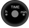
Figure 9: Time settings button.
When key TIME tone button was pressed, the min and sec will be cleared to 00. The correcting zone is -2 to +2 minutes. For example if current minute is 58 mins, the hour will be incremented by one. But if it is 02 mins, the hour will not change. This feature is the same as the original board. The h and min buttons also have repeat function when press more than 0.5s.
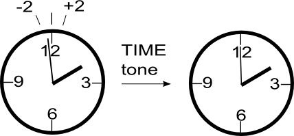
Figure 10: Time tone pressing.
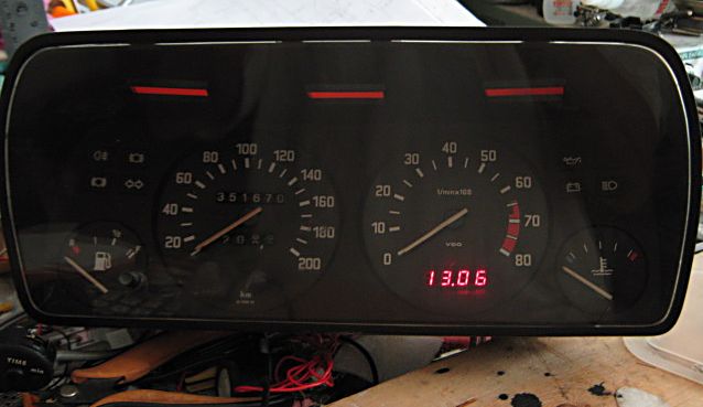
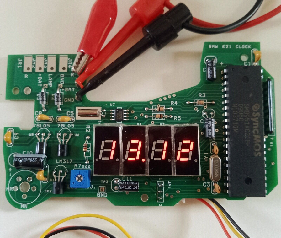
Figure 11: Reinstall in the E21 instrument console, powered with +12V Lab power supply.
Download
| Schematic | E21clock.pdf |
| C source code | N/A |
| Orcad Schematic File | N/A |
| Intel-Hex file | E21clock.hex |
BMW E21 Digital Clock Replacement kit

Available now on eBay for 24 or 12 clock format.
Free optional toggle switch for time setting
Classic look display, brightness is adjustable.
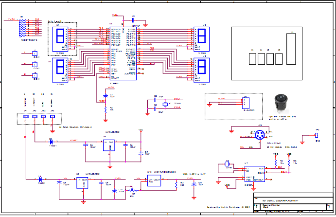
Complete schematic, click to enlarge
Download BMW E21 clock Quick Start , Hardware schematic
More information please contact wichit.sirichote@gmail.com
New PCB for left-hand E21
This new PCB will fit the left-hand drive E21 version. The circuit is the same with a bit modification on Time switch connector. The optional time setting toggle switch is available for easy time setting.
Here is the complete schematic, (click on schematic for larger view)
The real time clock chip is tied to battery power pin, while the R pin is from ignition, powered only when switch the car ON. R7 is for adjusting display brightness.
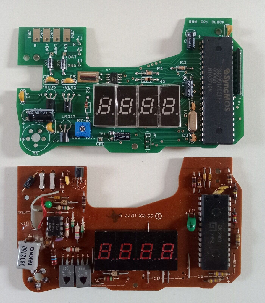
The photo shows comparison between the replacement board and the original board.
Download BMW E21 clock Quick Start , Hardware schematic for green PCB
More technical information, please contact Wichit Sirichote, wichit.sirichote@gmail.com
Last updated Feb, 2024
23 May 2010