Wichit Sirichote, kswichit@kmitl.ac.th
Build a generic instrument,
the Digital Voltmeter using the classic DVM chip, the Intersil ICL7135
and the 8051 compatible microcontroller.
I got the idea to design
the digital volt meter when I visited the scientific lab in school at Bangpain
district. I thought the lab should provide the generic instrument that
student can use it for many experiments. One of the generic instrument
is a digital volt meter. For example, when students make a simple battery
with lemon, they can measure the EMF and learn the different of using various
kinds of electrode. So I got back to 1982, when I was a university student,
I do remember the Intersil ICL7135 very clearly. This year 2011, almost
29 Years, the classic integrating type analog to digital converter is still
interested. With a cheap price and easy interfacing, I think I will design
a cheap digital volt meter with microcontroller to provide serial interface
similar to the Fluke45. Two channels is good for scientific experiment.
The serial port RS232 is also nice for interfacing to the PC. Let us see
the prototype of the meter in Figure 1. The display for each channel is
8-digit 7-segment LED. It is cheap and very reliable.
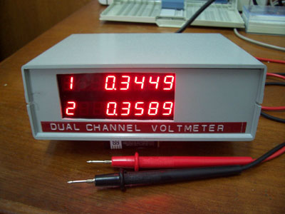 |
| Figure 1: The prototype of the Dual Channel Digital Volt Meter. |
The schematic block diagram
of the instrument is shown in Figure 2. Two digital volt meter chips, ICL7135
are interfacing to the 89S52 microcontroller. The ICL7135 is a 4.5 digital
volt meter chip using the integrating method. The input range is +/-1.9999V
with 100 uV sensitivity. The ICL7135 provides a multiplexed BCD output
and strobe signal (STRB). The microcontroller generates a 125kHz clock
for both DVM chips using timer2. When the conversion is completed, the
DVM chip generates strobe signal which in turn is used to interrupt the
89S52 to the external interrupt pins INT0 and INT1. The readings are sent
to the display board using MAX7219 and also sent to the PC using RS232,
9600 8n1.
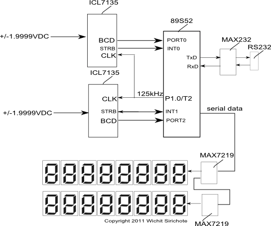 |
| Figure 2: Block diagram. |
The complete schematic is
shown in Figure 3. The BCD output from U1 the ICL7135 DVM, B1,B2,B3,B4
are tied to P0.0, P0.1, P0.2, P0.3. D5 is digit scan for the MSD. When
D5 is logic HIGH, the first BCD will be MSD. The microcontroller reads
the BCD output when the strobe signal is active LOW. This signal is used
to interrupt the microcontroller. With 5 pulses sequentially, all digits
will be read. The clock signal for 50Hz rejection is 125kHz (120kHz for
60Hz). It is generated by timer2 50% clock out mode. The reference voltage
+1.0000V is generated by the reference diode, LM385 or ICL8069. R3 adjusts
for +1.0000V. Integrating and AUTO zero capacitors are polypropylene type.
Three signals, LOAD, DIN and CLK tied to the P1.5, P1.6 and P1.7 are used
to connected the MAX7219 display board. The power supply circuit provides
+5V for digital logic, +5VA for analog circuit and -5VA for analog circuit.
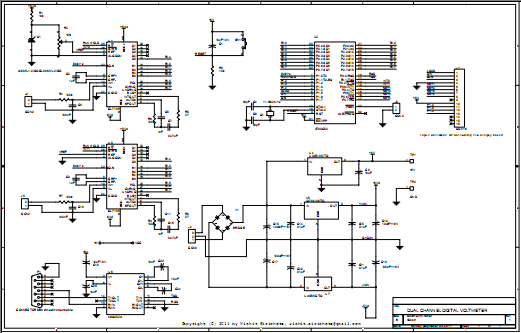 |
| Figure 3: Hardware schematic (click to enlarge). |
Figure 4 shows the display
board schematic using MAX7219. Each chip drives 8-digit 7-sement LED. The
serial data out from the 1st MAX7219 is tied to data in of the 2nd MAX7219.
This configuration forms the 32-bit shift register (the control byte and
data byte is 16-bit word).
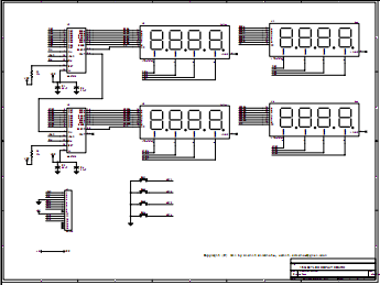 |
| Figure 4: The display board schematic. |
The source code listing is
shown in Figure 5. The main program is forever loop reading the BCD output
from the ICL7135 continuously.
/*
 DVM7135 Project
Dual Channel Digital Volt Meter Interfacing two ICL7135 4 1/2DVM chips to the 89S52 Microcontroller Signal input +/-1.9999V 100 uV sensitivity Serial interface: RS232C 9600 8n1 Power Supply: 220VAC 5VA Copyright(c) 2011 Wichit Sirichote, kswichit@kmitl.ac.th, September 5, 2011 This program is free software; you can redistribute it and/or modify it under the terms of the GNU General Public License as published by the Free Software Foundation; either version 2, or (at your option) any later version. This program is distributed in the hope that it will be useful, but WITHOUT ANY WARRANTY; without even the implied warranty of MERCHANTABILITY or FITNESS FOR A PARTICULAR PURPOSE. See the GNU General Public License for more details. */ #include "AT89X52.H" #include "stdio.h" sbit CLK= P1^7; sbit DIN= P1^6; sbit LOAD= P1^5; sbit D5 = P0^4; sbit P2D5 = P2^4; int digit=5; int digit2=5; char sbuffer[8]; char sbuffer2[8]; unsigned char buffer[16]; char command; short ready=0; short ready2=0; short terminal=1; int V1=0; int tV1,tV2; unsigned int temp16; unsigned long temp32=0; sbit RUN = P1^1; char code convert[10] = {0x7e,0x30,0x6d,0x79,0x33,0x5b,0x5f,0x70,0x7f,0x7b};
 /* 7-segment pattern converting array
   a
   __ register data
   f |__| b D7 D6 D5 D4 D3 D2 D1 D0
   e |__| c.DP DP a b c d e f g
   d
   */
char code prompt[] = "\n\r >"; short pol,ov; short pol2,ov2; #define POLARITY 0x20 #define OVERRANGE 0x40 // shift 32-bit data to 7219 serially shift(long n)
{
char j;
 CLK = LOAD = 0;
   for(j=0; j<32; j++)
   {
   DIN = n&0x80000000; // send data to 7219
   CLK =1; // pulse CLK
   CLK =0;
   n<<=1; // shift left one bit
   }
   LOAD =1; // pulse LOAD
   LOAD =0;
   }
init7219()
     {
   shift(0x0a010a01); /* intensity (middle) */
   shift(0x0b070b07); /* scan limit 8 digits */
   shift(0x09000900); /* no decode mode */
   shift(0x0f000f00); /* disable test mode */
   shift(0x0c010c01); /* normal operation */

   }
update7219()
     {
   //init7219(); /* reinitialize everytime entering to this function */
   temp32=0;
   temp32 |= buffer[0];
   temp32<<=16;
   temp32|= buffer[8];
   shift(0x01000100|temp32);
 temp32=0;
   temp32 |= buffer[1];
   temp32<<=16;
   temp32|= buffer[9];
   shift(0x02000200|temp32);

   temp32=0;
   temp32 |= buffer[2];
   temp32<<=16;
   temp32|= buffer[10];
   shift(0x03000300|temp32);

   temp32=0;
   temp32 |= buffer[3]|0x80; // put decimal point
   temp32<<=16;
   temp32|= buffer[11]|0x80;
   shift(0x04000400|temp32);
temp32=0; temp32 |= buffer[4]; temp32<<=16; temp32|= buffer[12]; shift(0x05000500|temp32); temp32=0; temp32 |= buffer[5]; temp32<<=16; temp32|= buffer[13]; shift(0x06000600|temp32); temp32=0; temp32 |= buffer[6]; temp32<<=16; temp32|= buffer[14]; shift(0x07000700|temp32); temp32=0; temp32 |= buffer[7]; temp32<<=16; temp32|= buffer[15]; shift(0x08000800|temp32); } void ex0_isr (void) interrupt 0 using 1
{
if(D5) digit=5;
sbuffer[digit]= P0&0x0F;
buffer[8-digit]=convert[sbuffer[digit]];
digit--;
if(digit==0) ready=1;
// read polarity, over range and under range
if(P0&POLARITY) pol=1;
else pol=0;
if(P0&OVERRANGE) ov=1;
else ov=0;
}
void ex1_isr (void) interrupt 2 using 2
     {
   if(P2D5) digit2=5;

   sbuffer2[digit2]= P2&0x0F;
   buffer[16-digit2]=convert[sbuffer2[digit2]];
   digit2--;
   if(digit2==0) ready2=1;
   // read polarity, over range and under range
   if(P2&POLARITY) pol2=1;
   else pol2=0;
   if(P2&OVERRANGE) ov2=1;
   else ov2=0;
   }
void over_display()
     {
   buffer[3]=0x7E;
   buffer[4]=0x0E;
   buffer[5]=0;
   buffer[6]=0;
   buffer[7]=0;
   }
void over_display2()
     {
   buffer[11]=0x7E;
   buffer[12]=0x0E;
   buffer[13]=0;
   buffer[14]=0;
   buffer[15]=0;
   }
void print_channel1()
     {
   // float temp;
   if(ready)
   {
   // ready=0;
   V1=0;
   V1 = sbuffer[5]*10000;
   V1 += sbuffer[4]*1000;
   V1 += sbuffer[3]*100;
   V1 += sbuffer[2]*10;
   V1 += sbuffer[1];
//RUN=0; // display on LED if(pol==0) buffer[2]= 0x01; // put minus sign else buffer[2]=0x00; buffer[3] |=0x80; // put dot to buffer[3] if(ov) over_display(); update7219(); // also send to PC via serial port 9600 8n1 if(pol==0) V1*=-1;
tV1= V1;
// printf("\n%.4f,",temp);
}
}
void print_channel2()
     {
     // float temp;
   if(ready2)
   {
   // ready2=0;
   V1=0;
   V1 = sbuffer2[5]*10000;
   V1 += sbuffer2[4]*1000;
   V1 += sbuffer2[3]*100;
   V1 += sbuffer2[2]*10;
   V1 += sbuffer2[1];
//RUN=0; // display on LED if(pol2==0) buffer[10]= 0x01; // put minus sign else buffer[10]=0x00; buffer[11] |=0x80; // put dot to buffer[3] if(ov2) over_display2(); update7219(); // also send to PC via serial port 9600 8n1 if(pol2==0) V1*=-1;
tV2= V1;
//printf("%.4f",temp);
}
}
void pause()
     {
   unsigned int i;
   for(i=0; i<50000;i++)
   continue;
   }
void print_7135()
     {

   //buffer[1]=0x06;
   //buffer[2]=0x4E;
   //buffer[3]=0x0E;
   buffer[12]=convert[7];
   buffer[13]=convert[1];
   buffer[14]=convert[3];
   buffer[15]=convert[5];
   update7219();
   pause(); // wait for a while
   }
void print_terminal()
     {
 if(ready&&ready2)
   {
   ready=0;
   ready2=0;
   printf("\n%dE-4,%dE-4",tV2,tV1);
} } char getchar(void)
{
char c;
while(!RI);
RI =0;
c = SBUF;
putchar(c); // echo to terminal
return SBUF;
}
void getcommand()
     {
   if (RI) command = getchar(); //
   else command = -1; /* no cammand has entered */
   }
void escape_command()
     {
   if(command== 0x27)
   {
   //terminal^=1;
   }
   }
void main (void)
     {
     SCON = 0x50; /* SCON: mode 1, 8-bit UART, enable rcvr */
     TMOD |= 0x20; /* TMOD: timer 1, mode 2, 8-bit reload */
     TH1 = 0xfd; /* TH1: reload value for 9600 baud */
     TR1 = 1; /* TR1: timer 1 run */
     TI = 1; /* TI: set TI to send first char of UART */
     T2CON = 0x00; // timer 2 is used to produce 120KHz for 60Hz and 125kHz for 50Hz
     T2MOD |= 0x02;
     TR2 =1;
     RCAP2H= 0xFF;
     RCAP2L= 0xEA; // E9 for 120kHz, EA for 125kHz
IT0 = 1; // Configure interrupt 0 for falling edge on /INT0 (P3.2) IT1 =1; // falling edge of INT1 EX0 = 1; // Enable EX0 Interrupt EX1 = 1; // enable EX1 interrupt EA = 1; // Enable Global Interrupt Flag RUN=1; // hold init7219(); printf("\nDual Channel Digital VoltMeter");
print_7135();
buffer[0] = convert[2];
     buffer[8]= convert[1];
while(1)
{
getcommand();
escape_command();
print_channel1();
print_channel2();
print_terminal();
} } |
| Figure 5: Source code listing. |
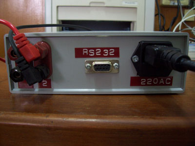 |
| Figure 6: The RS232 connector for connecting to the PC. |
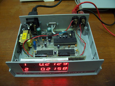 |
| Figure 7: The main board and display board inside the plastic box. |
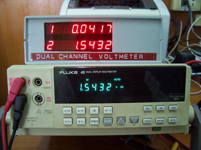 |
| Figure 8: Calibrated with Fluke 45 showing the EMF of 1.5V AA battery (shown in channel 2). |
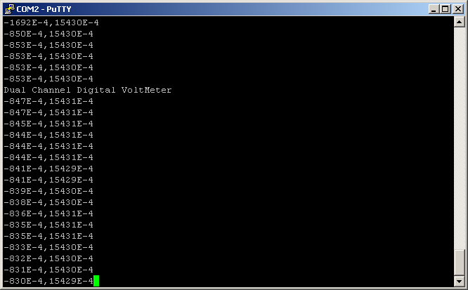 |
| Figure 9: Sample reading sent from the meter to the PC via the RS232 port. |
Figure 10 shows the EMF from lemon battery. Student can see the polarity
at the battery's electrodes.
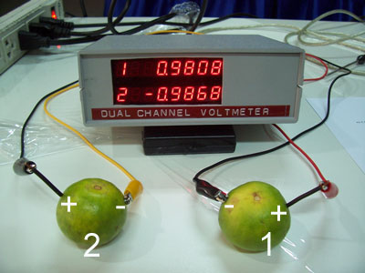 |
| Figure 10: Lemon battery using zinc coated nail and copper wire as the electrode. |
Now we can connect two batteries in series to increase the EMF, shown 1.9754V!
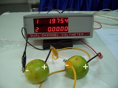
Figure
10: Series connected battery.
Download Schematic, Source code, HEX file (<-right click and save as) BOM
5 September 2011
Connecting the Voltmeter to a PC
The new firmware provides a means to connect the Voltmeter to a PC using RS232C. Student may uses a PC running terminal emulator program for data logging easily.
We can use the PuTTY for connecting the Voltmeter. For a notebook without the RS232 port, we can use the RS232-USB converter cable.
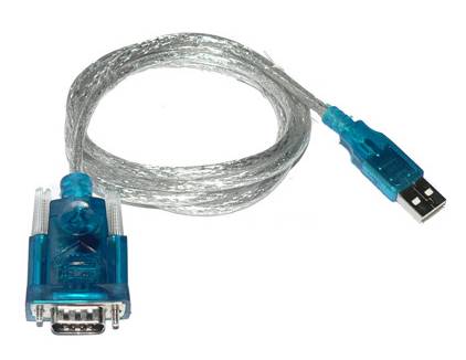
Figure
11:
RS232 to USB converter.
Run the PuTTY, it will ask for selecting the session. Select Serial port and set the COM port number.
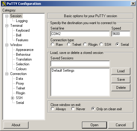
Figure
12: Select session to Serial interface.
For more options, click at Serial under SSH, select the flow control to None.
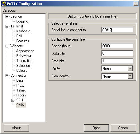
Connect the cable to a given port, says USB or direct COM port.
Click Open, the screen terminal will be appeared, press ENTER key followed with ? for help menu.
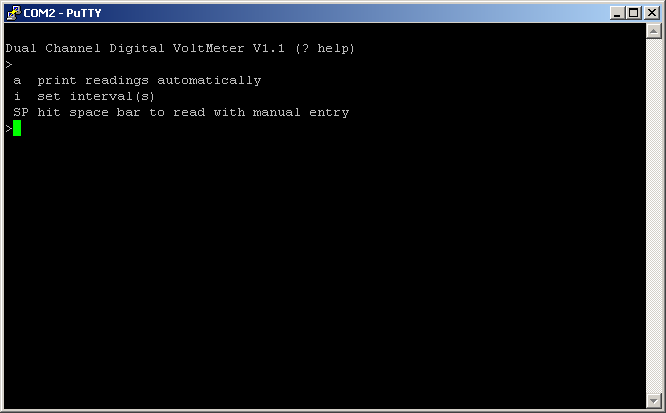
Figure
13: Help menu display.
There are three commands as follows.
1. command 'a' prints the
readings to the terminal with a programmable interval automatically.
2. command 'i' sets the
interval between sample to print using command 'a'. Default is 1 second.
3. Space bar hitting gets
the readings from both channels and wait for user entry the numeric data.
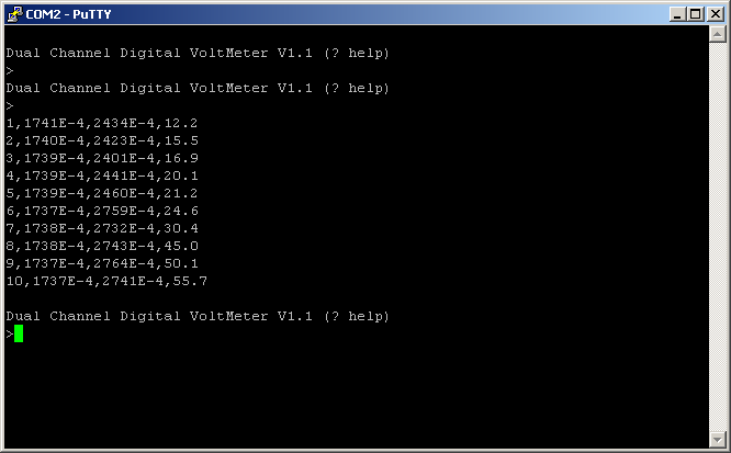
The example of using command 'a' and command 'i' is shown in Figure 14.
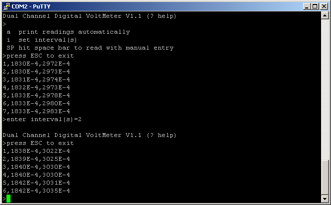
Figure
14: Print the readings to terminal automatically.
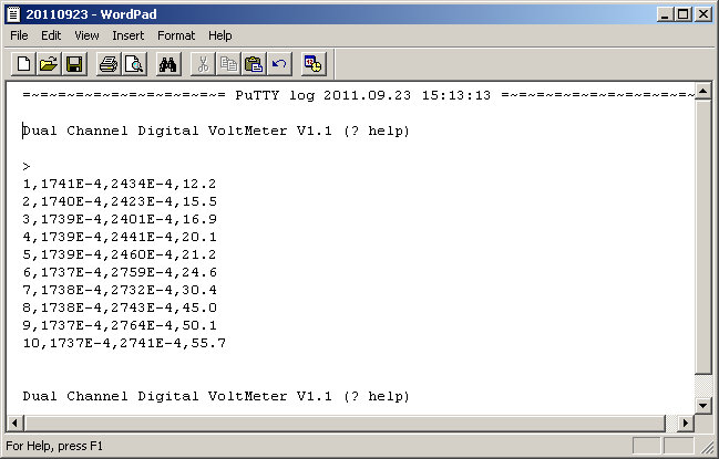
As shown in Figure 15, we can set the terminal to capture the printable text on the screen to a data file. PuTTY calls it as the LOG file.
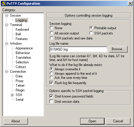
Figure
15: Setting LOG filename and session logging.
Go to Session---Logging, click at Printable output and type the file name. The example shown in Figure 15 uses Year, Month, Date to be the file name for easier finding the files.
For experiment that needs student to enter another variable at a given event, we can use space bar hitting with manual entry.
When the Space Bar was hit, the readings will appear on the screen and user can enter the numeric data with Enter key. For next sample, hit Space Bar again.
Figure
16: Event with entry mode.
When the session was closed, we will get the log data file as shown in Figure 17. The file is text file with comma separated value, thus it can be imported into the spreadsheet software easily.
Figure
17: Log file content.
Download Source code, HEX file
What's New? Adding Bluetooth Modem to the meter