6809 Microprocessor Kit
Wichit Sirichote, wichit.sirichote@gmail.com
Build a microcomputer training kit with the Motorola 6809 CPU. Updated monitor version3, User Manual and Programming book.!
I got suggestion from Didier to design the trainer kit with 6809 or 6309 microprocessor. So I spent my free time design this kit. The kit uses Motorola 68B09 as the CPU. I added the UART chip, 6850 ACIA. The circuit is simple and use small number of components. All decoder logics are placed in PLD chip. This makes the circuit is very easy to build. I found cc09 c compiler for 6809. The monitor was developed using c and assembly code. The main clock frequency is 4.9152MHz. UART chip uses E clock, 4.9152MHz/4 as the TXD/RXD clock. The prescaler is 64, so the UART will produce 19,200 bit/s rate. The 6809 has long branch using 16 bit offset. One of the monitor key provides 16-bit HEX calculator. Students can use it for finding the 8-bit or 16-bit offset. For low level coding, we can use hex key to enter and test the program. For c programming, we can use UART for S19 file downloading easily.
 |
| Figure
1: Motorola 6809 Microprocessor kit 2017 |
Hardware descriptions:
U5 is the Motorola 68B09 CPU. The 4.9152MHz is generated by onchip oscillator with internal frequency 1.228MHz for CPU operations. NMI, HALT, IRQ, FIRQ are pull-up to logic 1 with R2. Only E and R/W and A0,A1, A10-A15 are used for memory decoding.
U1 is 32kB EPROM, 27C256. The address space for EPROM is decoded at 0xC000-0xFFFF.
U2 is 32kB static RAM, 62256. The RAM space is located at 0x0000-0x7FFF. Zero page is located at 0x0000-0x00FF. User program can be tested from address 0x0200.
U4, memory and I/O spaces decoder chip is made with GAL16V8D. It provides chip selected signals for memory and I/O chips.
U3, the 20-pin 89C2051 microcontroller chip produces 10ms tick. SW1 selects between 10ms tick or manual IRQ button.
U6 is 6850 ACIA, UART. The shift clock is derived from E clock, 1228800Hz. Internal prescaler is 64. Thus the bit rate will be 19200 bit/s.
U12, 74HC541 is 8-bit input port (PORT0). Six bits, PA0-PA5 are input signals of the row keypad.
U10, 74HC573 is 8-bit output port (PORT2). The 8-bit output drives the 7-segment LED directly. No current limit resistor. U11 (PORT1) drives 6-digit common cathode pin. The brightness is controlled by software controlled PWM. PC7 is speaker output for beep signal.
U13, 74HC573 is 8-bit output port for 8-bit binary number display. D13 lifts the forward biasing for proper brightness. JR1 is 16-pin socket for text LCD interface. U14, HIN232 converts TTL level to RS232 level.
Q2, KIA7042 is reset chip for power brownout.
 |
| Figure
3: Hardware schematic (click to enlarge) |
Hardware Features:
-CPU: Motorola 68B09, 8-bit Microprocessor @1.2288MHz clock
-Memory: 32kB RAM, 16kB EPROM
-Memory and I/O Decoder chip: Programmable Logic Device GAL16V8D
-Display: high brightness 6-digit 7-segment LED
-Keyboard: 36 keys
-RS232 port: 6850 ACIA 19200 bit/s 8n1
-Debugging LED: 8-bit GPIO1 LED at location $8000
-Tick: 10ms tick produced by 89C2051 for time trigger experiment
-Text LCD interface: direct CPU bus interface text LCD
-Brownout reset: KIA7042 reset chip for power brownout reset
-Expansion header: 40-pin header
Monitor program was developed using c and assembly language. Source code was compiled with cc09, c compiler for 6809 CPU. The source code is available for customizing your own monitor.
The monitor program features:
-Simple hex code entering
-Insert and Delete byte
-User registers: A, B, X, Y, S, U, DP Condition code registers for storing CPU status after -program execution
-HEX calculator for offset calculation
-Copy block of memory
-Motorola s-record S19 downloading
-Memory dump
-Beep ON/OFF
-TEST 10ms
The monitor program will be updated and available for testing at the download links.
Keyboard layout: Making key layout sticker is simply done by printing the SVG file to sticker paper.

|
| Figure 6: Keyboard layout. |
Example of test code

Simple program that writes accumulator content to gpio1 LED at $8000. It will show 8-bit binary counting!
Delay1 is small delay subroutine that uses X register. We can enter the hex code into memory and test run directly.
Can you change speed faster? how?
Another example of using 10ms tick generator for counting binary at 1Hz rate. Change SW1 to 10ms tick.

The IRQ vector in ROM is pointed to new location in RAM at $7FF0. Students can modify where to put IRQ service routine. Above example uses location $6000 for IRQ service. The main code then inserts JMP to IRQ service instruction, 7E 60 00 to location 7FF0. Then clear I flag and wait for interrupt.
The IRQ service uses location 0 for tick counting. When it reaches 100, clear it and increment location 1. We can see 1Hz rate counting of location 1 by sending it to gpio1 LED at location 8000.
Can you change from 1Hz to 10Hz counting rate, how?

Example of using Tera Terminal with key DUMP.

S-record file transfer with 1ms character delay setting.

Figure 7: With Big letter LCD.
|
PARTS LIST
Semiconductors
U1 27C256, 32kB Eprom
U2 HM62256B, 32kB SRAM
U3 AT89C2051, 8-bit microcontroller
U4 GAL16V8D, PLD
U5 Motorola 68B09, 8-bit microprocessor
U6 Motorola 6850, ACIA chip
U7 7805, voltage regulator
U9,U8 LTC-4727, 7-segment display
U10,U11,U13 74HC573
U12 74HC541
U14 HIN232, RS232 converterQ1 BC557
Q2 KIA7045
Q3 BC557 D4 1N4007
D13 1N5227A
D14 1N4733A D1,D5,D6,D7,D8,D9,D10, LED
D11,D12
D3 POWER LED
Resistors (all resistors are 1/8W +/-5%)
R1 680
R2 RESISTOR SIP 9
R3 100
R13,R4 10k
R6,R5 1k
R9,R7 4.7k
R11,R8 10k RESISTOR SIP 9
R12,R10 10
Capacitors
C1,C4,C5,C15,C18,C19,C20 10uF
C3,C2 27pF
C6 10uF 16V
C7 1000uF25V
C8,C9,C10,C11,C12 0.1uF
C13,C14 0.1uF
C21,C16 100nF
C17 10uF 10V
Additional parts
JP1 HEADER 20X2
JR1 CONN RECT 16
J1 DC Input
J2 CON3
J3 CON4A
LS1 SPEAKERSW1 ESP switch
SW2 IRQ
SW3 RESET
SW4 FIRQ
SW5 NMI
S1,S2,S3,S4,S5,S6,S7,S8, SW PUSHBUTTON
S9,S10,S11,S12,S13,S14,
S15,S16,S17,S18,S19,S20,
S21,S22,S23,S24,S25,S26,
S27,S28,S29,S30,S31,S32
TP1,TP2,TP3 TEST POINT
TP4 +5V
TP5 GND
VB1 SUB-D 9, Male (cross cable)
Y1 4.9152MHz XTAL
PCB double side plate through hole
display filter sheet, Amber color
Keyboard sticker printable SVG file
|
|
Kit is available on ebay. More information please contact Wichit Sirichote |
Download Schematic, Monitor source code , Monitor listing, PLD files, AT89C2051 HEX file,
Keypad SVG file , Quick start
Programming Book for 6809 Kit rev 1.2 March 2018,
6809 Kit User's Manual rev 1 April 2020, Tools and assembly source code
Programming Book for 6809 Kit Rev.2.0 April, 2020 updated monitor call adress with latest monitor program.
What's New?
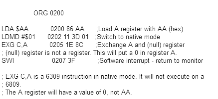
July, 2023, Note on experimenting the Hitachi 6309 CPU by Mendel Cooper.
With a genuine 6309 executing the program returns to the monitor, and the A register contains a value other than AA, usually 0. With a 6809 the program jumps into hyperspace, and results in a blank LED display, until Reset is pressed.
16 May 2020, updated new monitor by Edilert Kirk with 20x4 LCD display for hex editor and user registers display, newmon1.zip


11 May 2020, Modified version of new monitor by Thomas Winkler, remapped the ROM and I/O locations to make more ROM space, 03-30K.zip
0000 - 7FFF
8800 - FFFF
8000 - 87FF
8800 - 8FFF |
system RAM (32 KB)
system ROM (30 KB)
IO (read write)
IO (write only) |
9 May, 2020 New design 6809's keypad sheet, designed by Hark0, Jordi Bayo', Corel draw file, Inscape 0.92 File

3 May, 2020 New monitor program written in 6809 assembly code with BS9 Assembler by Edilbert Kirk. Super fast s19 downloading source and listing (pdf files), ROM files
23 April, 2020 updated monitor program, set user DP register to 0 when RESET, Source code, list file and hex file for 32kB EPROM.
27 March, 2020 updated montior program, fixed Motorola s-record loading. Source code, HEX file ready for programming the 32kB EPROM. Thanks to Thomas Winkler for bug report.
14 February, 2020 The 6809 kit has been tested with the Hitachi 63C09 microprocessor by Edilbert Kirk. Edilbert wrote his own Cross Assembler for 6309 CPU, https://github.com/Edilbert/BS9


6809 Technical documents and tools in French
Nov 2024, updated 6809 tools by Richard Sorek
Latest 6809 tools by Richard Sorek (in French)
Assembler-disassembler for 6809, by Richard Sorek (text in French)
Updated 6809 book by Richard SOREK, v4.13 (in French, 238 pages)
6809 Assembly Programming (in French, 247 pages) written by Richard SOREK
Book is available on request by sending mail to
keros6809@gmail.com
MICRO09KEY.stl keyboard spacer 3D file for 6809 kit made by Lucien Gisclong, giscl@free.fr


<

